This is a walkthru, from concept to completion, of how to build a Unity3D scene and map the visuals onto a meatspace object (in this case, a LED cube). It uses Unity3D, Spout, and Resolume.
Contents:
- Step 1: Set up the PixLite LED controller
- Step 2: Set up our media server (Resolume) to use ArtNet
- Step 3: Map our ArtNet universes in Resolume
- Step 4: Get Unity to communicate with our media server (Resolume)
- Step 5: Build our Unity Scene and map cameras to our LED universes!
- Step 6: Troubleshooting and next steps!
Overview:
The field of live visuals generation has evolved past flat video projections on a screen– it can incorporate architechture, lighting design, and customised LEDs built into staging or sculptural installations. Since most current visuals software supports 3D models and objects in some capacity, it’s natural for artists to use game engines when creating content for architecturally challenging events.
Unity3D is a game engine with a large support community and robust support for 3D objects and environments, and as such is well suited for building dynamic and complex visuals. With some careful planning, these visuals can be sent to most commercial VJ applications and then mapped to real-world fixtures and staging elements, either as projections or as LEDs in 3-dimensional space (voxels).
This walkthru will cover my build process, from concept to completion, of “Sparklebox”, a live visuals generation platform that maps Unity3D visuals in a virtual space onto a 6x6x9 foot cube. 3D objects are then mapped to individual LED pixels, allowing artists to make dynamic 3D content in meatspace.
Topics to be covered: Live visuals creation in Unity3D and Resolume, Spout for Unity and Resolume, LED fixture mapping, ArtNet networking, LED pixel controllers (PixLite 16).
This walkthru assumes a basic knowledge of 3D modeling, live visuals applications, networking. Working knowledge of Unity 3D and Resolume Arena is helpful, but not required.
ABOUT UNITY
from unity3d.com: “The Unity Editor is a creative hub for artists, designers, developers and other team members. Available on Windows and Mac, it includes 2D and 3D scene design tools, instant play mode for rapid editing and iteration, and a powerful animation system.”
For those who don’t know, basically, it’s a pro-sumer game engine. I like it because there’s a huge community for it– any problems you’re having with your build, someone has already fixed it (probably). You can download a full featured version, Pro versions have more robust network and version tracking support.
About Resolume
Resolume.com is a video mixing software program with a ton of features– pixel mapping, DMX control, video mixing and playback, and various types of plugin support. You can download a full featured (but watermarked) demo version.
About the Pixlite 16
From advateklights.com: The Pixlite 16 is a fully assembled RGB pixel mapping controller that can control 5,440 RGB pixels OR 4096 RGBW pixels and 4 DMX512 universe outputs. (36 Universes of input data.) The PixLite16 controller supports input protocols via an ethernet connection and displays RGB color lighting on TLS3001, SM16716, LPD6803, WS2801, WS2811/12/12B/APA104, TM180x, MBI6020, INK1003, APA102, SK6812, UCS1903, MY9221, MY9231. chipsets. It supports the following input protocols: sACN (E1.31) and Art-net.
About Spout
Spout is a realtime video sharing framework for Windows. Senders and receivers include FreeframeGL plugins, a Java interface for Processing, Jitter externals for Max/Msp, VIZZable, modules for Ableton Live, and a Virtual Webcam as a universal receiver. There is also example code for creating your own applications with openFrameworks and Cinder. Now these applications running on Windows can share video with each other in a similar way to Syphon for OSX.
About this tutorial
Use this tutorial however you want, feel free to add to it, be sure to forward it to whomever and give it away for free. If you charge some lazy bastard for this tutorial, you suck. If you use it for a performance and you make money– you rock! If you have some questions, advice, or praise, contact me at: info(at)ericmedine(dot)com
About Eric Medine:
Eric Medine is a multimedia and video artist and CEO of TenTon Raygun. He has shown work in galleries and museums such as the Track 16 Gallery in Santa Monica, Walled Cities Gallery in San Pedro, Andrew Shire Gallery, the Museum of Contemporary Art in Los Angeles, xm:lab and the KuustlerHaus in Germany, Los Angeles Contemporary Exhibitions, the Chicago Motion Graphics Festival, Faites de la Lumieres, and the LPM festival in Rome and Mexico City.
As a VJ and live visuals engineer he’s worked with performers such as Major Lazer, Meat Beat Manifesto, the Orb, Batchass, Lila Downs, Infected Mushroom, Excision, Wet Mango, Trash 80, Dan Wilcox, MegaRan, and Grammatik.
What you will need:
– Computer
- Windows 10
- i7 Processor, 2.5 GHz
- Nvidia GTX 1080
- M2 SSD
- 16 GB Ram
Downloads:
Spout:
Spout for Unity:
Resolume:
Unity3D
STEP 1 Let’s get down to it, boppers! Set up our PixLite control board and make sure it can control LEDs
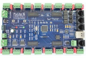
I’m using a PixLite 16 pixel control board, which allows you to send ArtNet data to your LED lighting fixtures over ethernet. This is SUPER handy for use cases when you have a custom LED setup, but probably overkill if all you’re doing is playing with some basic DMX controlled lights.
The main thing is that Resolume sees control boards like this quite handily. So first we start up Resolume and set up our fixtures. Once that’s done, we should be seeing beautiful LEDs being controlled by our video.
NOTE: There’s tons of other controllers out there (the Falcon pixel controller is reportedly quite good) and an equal amount of ways to connect DMX/ArtNet to led fixtures, but these methods are well beyond the scope of this walkthru.
I advise you to read the documentation about the PixLite, but short version is that you want to install the drivers AND the Advatek assistant software (download here: http://www.advateklights.com/resources/) and it should find the Pixlite for you automagically, as well as any LEDs you have hooked up to it.
It didn’t work quite that seamlessly for me on the first go-round, so here’s some things I tested first:
- Does it have enough power? I first tried using a wall-wart that put out enough power to run an arduino board and an LED strip, but NOT enough to run the pixLite and an LED strip. The Advatek assistant would find the board, but as soon as I tried to run a test on the strip it would power down and lose the network connection. Get yourself a decent power supply. I used the TekPower TP1540E DC Adjustable Switching Power Supply 15V 40A Digital Display
- Are you using a router? In theory you can plug it directly into your laptop, but my personal experience is that it’s not worth the configuration hassle and it’s not particularly robust.
- Have you blown a fuse yet? I did that, like first thing. If you hook the LED strip up wrong (look at the direction of the arrows!) you might blow a fuse. Easily replaceable.
- Is your LED strip burned out? It’s super easy to do.
Regardless, you should be able to see your PixLite when you select the correct IP address in the “Select Adapter” tab, then hit “Search”. If you’re having trouble with this then refer to the manual for troubleshooting.
Once that’s done the default settings will probably need to be changed– for instance, you want to make sure that the chipset is selected correctly in the LEDs tab. Your LED strip should say what chipset it is, or at least whoever sold it to you should have that information. You may also want to write down the IP address, you might need that later when connecting to Resolume.
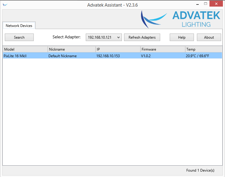
Here’s where you can see the IP address. Notice it tells you the temperature of the board as well as the ip and firmware version

One thing that’s super nice about the Advatek software is that it allows for a TON of control over your strips. You can set the type (chipset), color space of each strip (sometimes you’ll get a strip that’s wired in reverse: it’s GRB instead of RGB, etc), number of LEDs you want to use on each strip (this becomes important later on) and a ton of other settings.
Most important, you can run test patterns to make sure you’re getting signal and that the color space is correct.
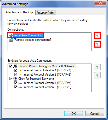
Here’s a stupid tho. If you’re running the Pixlite you’re probably doing it with a wired ethernet connection. However, you’ll find that if you try to use a WIRED connection at the same time as a WIRELESS connection, Windows wants to ignore the wireless connection. This is a real headache if you want to be looking up troubleshooting tips online at the same time you’re running LEDs. To fix this you need to change the order in which you go online– basically tell your windows box that you want to prioritize the WIFI connection data for internet over the WIRED connection data.
Here’s a tutorial for windows 7: https://support.microsoft.com/en-us/help/2526067
and one for windows 10: https://answers.microsoft.com/en-us/windows/forum/windows_10-networking/adapter-priority-setting-unavailable-in-windows-10/d2b63caa-e77c-4b46-88b5-eeeaee00c306

Now that we have sucessfully connected our PixLite to our computer, checked to make sure it’s configured correctly, and can see the LEDS that are plugged into it, we will now get Resolume to talk to the PixLite.
STEP 2 Set up Resolume to communicate with the PixLite 16
Let’s go ahead and connect to Resolume! This SHOULD be fairly painless, but there’s a couple caveats and gotchas that we’ll have to get through. Resolume’s preferred method of communication to DMX devices is ArtNet. Here’s a link to the documentation: https://resolume.com/manual/en/r5/dmx_output
Basically, ArtNet is a protocol that allows you to send data as little IP packets to lighting boards/fixtures over ethernet. It seems to be the new standard, which means that Resolume is really well positioned to be working with lighting designers.
First thing is to understand how Resolume handles DMX. I’m not really going to get into the history or applications of DMX outside this particular use-case but here’s a link to an overview: http://dmxusb.com/what-is-dmx/
DMX protocol revolves around “Universes” that hold 512 channels each, and each channel holds a packet of data (for this application each channel will represent a LED), so Resolume needs a way to assign its output to this format. It creates a “Lumiverse” that is basically a virtual DMX universe, allowing Rez to assign whatever information it wants. So the first thing we want to do is create a new Lumiverse that will correspond to a particular LED strip (in Resolume terms a piece of LED gear is called a “Fixture”) that we’ve hooked into the PixLite. Then we’ll assign the “Lumiverse” to one of the outputs for the PixLite in the DMX preferences… and then repeat 15 times (16 outputs).
Unfortunately, this means math, since we need to make sure our fixtures have the same amount of channels/leds as our strip. Fortunately, the math isn’t that hard!

First, go to “Arena > Fixture editor” to set up our custom LED fixture. Resolume has a default DMX pixel tube, but we’re not using that. Let’s make a custom one– our strip is 150 leds long, and the chipset is WS212b, so let’s call it “WS212b 150px”.
You’ll notice that you can set the RGB color space and gamma separately here, which is SUPER helpful for reasons I’ll explain later. If we were using a LED curtain our fixture would have a height as well as a width.

Now that we have a fixture saved, let’s create a “Lumiverse” that uses this particular fixture. Then, we’ll assign that lumiverse to a specific DMX output. Since a Lumiverse is the same thing as an output screen, we will create one in the “Output > Advanced Output” window in Resolume.
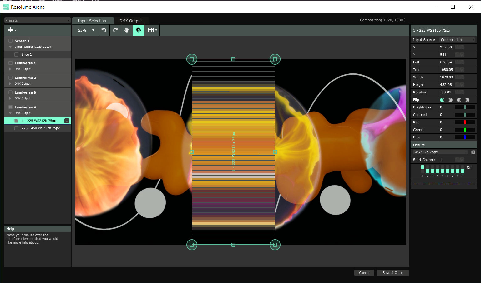
It’s pretty simple– Resolume automagically assigns the right universe, and you can select the correct fixture that we made earlier (Ws2812b 150px) in the dropdown. You’ll notice that I’m actually using a fixture that’s only 75 leds long. I’ll get to that later.
In addition, you now have a preview of what the LED strip will look like– Resolume maps and averages the color across the correct fixture. Now let’s assign this fixture to an actual output!
Go to “Preferences>DMX” and add a new output. You’ll see a bunch of choices: Device, Lumiverse type, Subnet, Universe, Target IP. We really only need to worry about the type of lumiverse, its subnet/universe, and IP address. Subnet/universe corresponds to the output on the Pixlite (basically we have 2 rows of 8 outputs, marked 1-16… but we’re ACTUALLY assigning our outputs as subnet 0 universe 1-15 odd numbers, subnet 1 universe 2-14 even numbers).
So (assuming we’ve plugged our LED strip into output 1) we’ll select Lumiverse 1, set the subnet to 0 and the universe to 1, and then use the target IP to find our PixLite.

The target IP thing can be tricky. If you’re using a router (and you SHOULD be using a router) then you should see the PixLite by name. Sometimes you won’t depending on how many ethernet connections you have, but selecting “Broadcast” sometimes fixes that– it just blasts ArtNet data to every available universe and the Pixlite will pick it up.
However, I’ve found a bug in Resolume where it will “see” the pixlite (and know its address) but won’t be able to select it. If that’s the case, you can type the IP address in manually (look it up in the Advatek assistant) and that should work as well.
You shold now be seeing the video signal mapped to your LED strip!
This is all well and good, but we don’t want to just play some video on our strips, we want generative 3D visuals! To do that, we’re gonna have to add a bunch more LED strips and make sure they’re mapped consistently.
STEP 3 Map our pixels correctly in Resolume
So, we should be seeing a bunch of lights flashing on a single LED strip, but as soon as we start adding strips things become a little more complicated.
First, let’s figure out exactly how we want to hang these strips to have the optimal setup. Your own installation will vary as far as wiring and other configurations, but some of these issues will come up regardless.
The Pixlite has 16 outputs, so figure we can most easily have a 4×4 grid of LEDs– each output is a vertical strip of whatever length. However, we can increase this number with a little planning– simply have the outputs handle more than one vertical!
In general you need to inject power every 100 or 15o leds. Most consumer type LED strip will come in that type of length, and since each output of the PixLite also handles power we should be able to cut each strip in half, doubling our horizontal resolution without needing to add extra power.
In the diagram you can see two different configurations– one with 150 LEDS per output, the other with two sets of 75 LEDs per output.
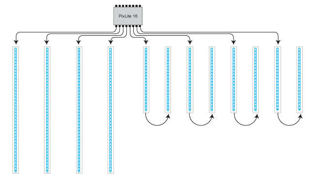
The cutting strips in half is the trivial part– the more complicated is to handle the mapping for it. Since instead of a single 150 LED strip/150 pixel fixture per Lumiverse, we’re going to have TWO 75 pixel fixtures per Lumiverse and then virtualy rotate one of the pair 180 degrees so the mapping will be consistent.

For instance, let’s say we have some video that’s multiple colors– for instance if we have a big red bar across the bottom half of our Lumiverse, configuration A will display it incorrectly, but configuration B will look right because we’ve “rotated” every other fixture in virtual space.

Go into the “Fixture Editor” (or click on the “settings” button near the fixture info in Advanced Output) and make a new fixture that’s only 75 pixels. Then go back into Advanced Ouptut and switch the type of fixture your Lumiverse is using. Then duplicate it– you should see that Resolume has automatically started the channel for the new fixture immediately after the previous fixture. Rotate the fixture in the output window, line it up, and you’ll see your video mapped correctly across multiple LEDs.
Additionally, you can make a new fixture then tell it to run the other direction in it’s settings, which is probably the smartest way to do it. There may be performance reasons to change it in the preferences rather than rotate the fixture itself, but I haven’t noticed any.
Regardless of how you handle the mapping , you’ll then do that for every single output for every single fixture. It’s not super fun. Luckily you can duplicate an entire Lumiverse, but you’ll STILL have to create a new output in the DMX preferences window.
STEP 4 Get Unity to talk to Resolume
Now let’s get Unity to talk to Resolume.
First, download Unity3D and Spout for unity. Next, download and install the Spout installer from GitHub at http://spout.zeal.co/
Next, let’s make sure Resolume “sees” Spout. After you’ve installed the most current version of Spout (as of this writing it’s 2.0) go ahead and run “SpoutSender.exe” in the “DEMO” folder. You should see a soothing cube rotating slowly. Or, you’ll get a bunch of crashes and “.dll not found” messages. Chances are (hopefully) that you just need to make sure your version of JAVA is current, or that you’re not running 32 bit instead of 64 bit (or is it the other way around? You should be trying to run 64 bit)
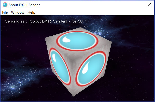
If you have Resolume up and running, go to “Sources” and you should see “Spout DX11 Sender”. Drag that guy into your deck and you should see the same soothing cube rotating as a video feed.

Success!
Now for the tough part. We have to get the custom Spout sender asset working correctly in Unity, and it takes a little bit of fussing. Basically, Spout sends video (or whatever) using texture sharing, so most of the issues we’ll run into (besides “library not found” runtime errors) will have to do with finding the correct textures.
We have the “Spout4Unity-master” folder all ready to go, downloaded and unzipped, right? Make a new Unity project. Go into the “Assets” folder (which should be empty) and drag “Spout” from the “Spout4Unity-master” folder in there.
You’ll also have to drag the “Plugins” folder in there to make sure Unity can find all the materials, compile all the DLLs, etc. Once you do that, run the scene by hitting the “play” button and your scene should run…

… if you go to Resolume, however, you’ll see a new source: “UnitySender0”. Wowee! That is the view of a 3D unity environment from your Unity camera running as a video source!

STEP 5 Now let’s map our 3D slices to our LED slices!
What we have now is a SpoutCam in a Unity scene that is sending everything it sees to Resolume. However, we don’t want the ENTIRE scene sent, just the information that we want displayed on a particular LED row.
For instance, if we have five rows of LED strips, we want each one to show five “sections” of our image… one section for each row.
Like this horse.

How do we do this? Well, we can’t really slice the image up so let’s use multiple Spout cameras, each one taking a different segment of the image.
It’s important to set the focus and angle of each camera so they don’t “overlap” as well.
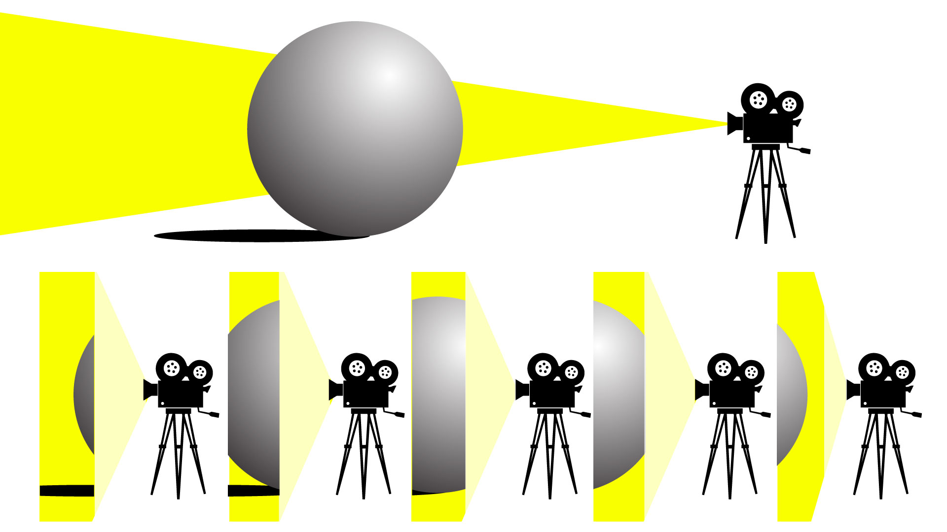
Each camera will then be mapped to a “row” of LEDs, and that’s how we’ll get proper 3D mapping.
This takes a little bit of prep. First let’s get the sizes right (more or less). Unity really likes its own units of measurements, so let’s just assume that one Unity unit is a foot. Or a meter, depending. I’ve more or less configured things to be on a 6×6 grid for demo purposes, so that’s what we’ll do– a 6x6x6 grid. Let’s go ahead and build a box like that, so when we have solid objects they have a place to bounce around.
Now we can just duplicate the cameras, making sure the positioning and whatnot is consistent. We’ve built slices!
To make this work, we need to do the following:
- set clipping planes (near and far)
- set alpha type to be “premultiplied” (I’m not 100% what this does, but it seems like it makes sure the background of the unity camera will be alpha’d out)
- set up layer routers in Resolume and make sure each layer has the correct camera assigned
- make a “blocker” solid color in Resolume so we’re only sending LED data to one “row” of LEDs (and one layer) at a time
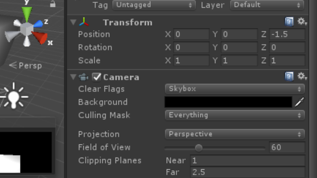
First, clipping planes! A clipping plane is the bounds of the camera’s viewable angle, and it’s how we get slices. It’s pretty trivial to implement– just select a camera in Unity and set its parameters in its “properties” window. For instance, let’s say we have 5 cameras that are set 1.5 “unity units” apart from each other– one with a z-position of 0, the next at 1.5, the next at 3, the next at 4.5, etc.
We’ll want the difference between the “near” and “far” view to be 1.5 so as not to overlap their viewpoints! This also means that are slices are kind of “thick”, in theory our slices/cameras should only be 1px apart… but this project is fairly low resolution.
Now that you’ve set your clipping planes, you’ll want to set up your Resolume project to route the cameras to the correct LED outputs. To do that we’ll set up multiple layers, each with a UnitySender that corresponds to a Lumiverse Input Source in the Advanced Output of Resolume (remember when you configured the Lumiverses?)
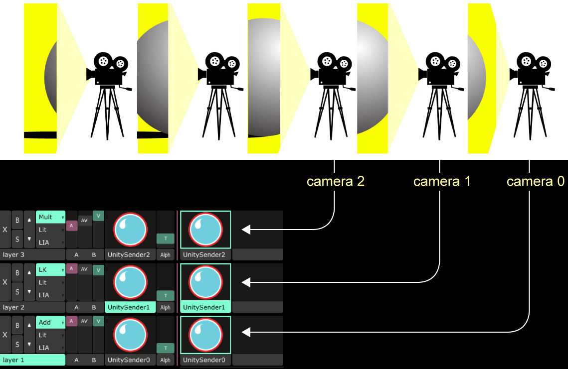
To continue with our hypothetical project, Camera 0 at z-position at 0 renders in Resolume as “UnitySender0”, Camera 1 at z-position 1.5 renders as “UnitySender1”, etc. So in Resolume, we’ll put our Spout Unity Sender0 into Layer 1 (for programming reasons I like a list of things to start with 0– like camera0, but Resolume starts with 1– like Layer 1).
Then we go into Advanced Output and tell set the Input Source for the fixtures for Lumiverse 0 (that handles our first row of LEDs) to render Layer 1. Then do this for ALL the other inputs.
Probably at some point you should save your Unity project as a nice prefab so centering is fairly trivial. Also, if you want to export this or give to someone else it’s easier if there’s a prefab.
STEP 6 Troubleshooting, tips, and cleanup!
Notice that our 3D objects are not solid? That there’s a “hole” in your LED wall? WHAT COULD THAT BE? Backface culling my darlings. Think about it– your solid 3D object in Unity is not actually solid… it’s a hollow shape with a texture or color map on it.
As soon as the camera goes “inside” there’s nothing to see. You can make the texture appear on the inside as well as the outside of your object, but it doesn’t completely solve the problem.
Easiest quick and dirty solution…. use particles. More difficult way… custom lighting effects or volumetric shaders. Does anyone know how to use those? I don’t. But I betcha there’s a plugin in the Unity store that does it.